
Structural Composition and Core Components of Screw Jacks
2025-09-22 08:46:22
Click:
“
Screw jacks, also known as spiral lifts or lead screw actuators, are critical me
”
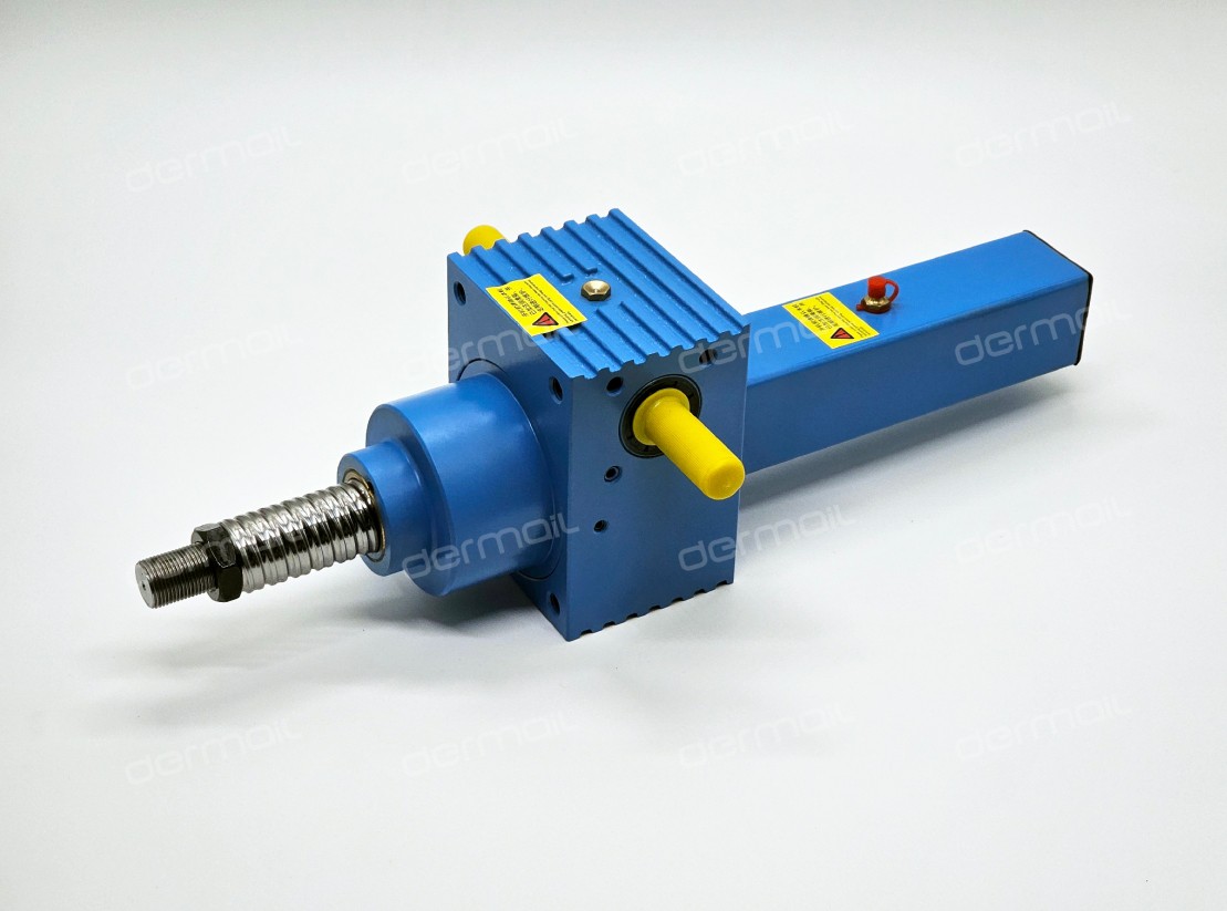
Screw jacks, also known as spiral lifts or lead screw actuators, are critical mechanical devices that convert rotational motion into linear motion. These devices are widely used in industrial automation, heavy machinery, precision equipment, and construction sectors due to their high load-bearing capacity, precise positioning, and compact design. This article provides an in-depth analysis of the main structural components of screw jacks and their functional relationships.
1. Core Transmission Mechanism: Screw-Nut Pair
The screw-nut pair serves as the heart of the screw jack, directly responsible for motion conversion and load transmission. Based on friction type, it can be classified into two categories:
1.1 Trapezoidal Screw Pair (Sliding Friction)
- Material: Typically made of alloy steel with precision grinding and heat treatment to ensure surface hardness (HRC 58-62) and wear resistance.
- Thread Profile: Standard trapezoidal threads (e.g., Tr32×6) with a 30° included angle, providing self-locking capability under static loads.
- Applications: Ideal for low-speed (≤0.5 m/min), high-load scenarios such as heavy-duty lifting platforms and large-scale mold adjustment. The JWM series trapezoidal screw jacks, for instance, can achieve 120 tons of static load capacity with a self-locking angle of 4.5°.
- Limitations: Lower transmission efficiency (30-40%) due to sliding friction, requiring regular lubrication maintenance.
1.2 Ball Screw Pair (Rolling Friction)
- Structure: Features precision-ground ball tracks filled with recirculating ball bearings, reducing friction coefficient to 0.003-0.01.
- Performance: Transmission efficiency reaches 92-98%, enabling back-drivable operation and sub-micron positioning accuracy.
- Applications: High-speed (up to 2 m/s) precision systems like CNC machine tool feed tables and semiconductor wafer handlers. The SWL series ball screw jacks achieve 0.01mm repeatability with 10-year service life under proper maintenance.
- Limitations: Requires precise manufacturing (IT5 grade) and cannot self-lock, necessitating additional brake systems for vertical applications.
2. Power Transmission System: Reduction Gearbox
The dermail transmission gearbox converts high-speed motor rotation into low-speed, high-torque output required for screw rotation. Two主流 designs dominate the market:
2.1 Worm Gear Reducer
- Configuration: Consists of a hardened steel worm (Z1=1-4 teeth) meshing with a bronze worm wheel (Z2=30-100 teeth).
- Characteristics:
- Single-stage reduction ratios up to 1:100
- Self-locking when lead angle <5°
- Typical efficiency of 60-70%
- Applications: Vertical lifting systems requiring inherent safety, such as theater stage lifts and parking equipment.
2.2 Planetary Gear Reducer
- Structure: Features three planet gears simultaneously engaging sun and ring gears, achieving compact design with high torque density.
- Performance:
- Reduction ratios from 3:1 to 1000:1
- Efficiency exceeding 95%
- Radial load capacity up to 500kN
- Applications: High-precision robotic arms and wind turbine pitch control systems.
3. Support and Guidance System
To ensure linear motion accuracy, screw jacks incorporate specialized support structures:
3.1 Fixed Support (Type FK)
- Design: One end of the screw is fixed to the housing via angular contact bearings, allowing only axial movement of the nut.
- Advantages: Eliminates screw sagging, suitable for long-stroke applications (up to 6m).
- Example: The SWL25-M-II-A model uses double-row tapered roller bearings to withstand 250kN axial load.
3.2 Floating Support (Type FF)
- Configuration: Both screw ends are supported by deep groove ball bearings, enabling thermal expansion compensation.
- Applications: High-temperature environments like metal smelting equipment, where thermal elongation can reach 3mm/m.
3.3 Nut Guidance Mechanism
- Linear Guide Rails: Integrate precision-ground rails with self-lubricating sliders to prevent nut rotation.
- Key Parameters:
- Guide rail accuracy grade: P3 (±0.005mm/m)
- Preload adjustment range: 0-5% of dynamic load
- Applications: Laser cutting machine Z-axis systems requiring ±0.01mm positioning.
4. Safety and Control System
Modern screw jacks incorporate multiple safety features:
4.1 Mechanical Limit Switches
- Function: Cut power when the nut reaches preset travel limits (typically ±1mm tolerance).
- Implementation: Uses proximity sensors or mechanical plungers to trigger contactors.
4.2 Overload Protection
- Torque Limiters: Employ spring-loaded friction plates that slip at 150% rated torque.
- Current Monitoring: PLC-based systems that halt operation when motor current exceeds FLA×1.2 for 5 seconds.
4.3 Position Feedback
- Incremental Encoders: Provide 1000-10000 pulses/revolution resolution for closed-loop control.
- Absolute Encoders: Offer battery-backed position memory, critical for power-failure recovery scenarios.
5. Structural Variants and Customization
Manufacturers offer modular designs to meet diverse requirements:
5.1 Double-Stage Screw Jacks
- Configuration: Two screws connected via coupling nuts, doubling the stroke length (up to 12m).
- Synchronization: Achieved through servo motor control with ±0.1mm parallelism.
5.2 Bevel Gear Dividers
- Function: Distribute motion to multiple output screws at 90° angles.
- Applications: Large-scale solar tracking systems requiring 16-point sun alignment.
5.3 Corrosion-Resistant Designs
- Materials: 316L stainless steel screws with PTFE-coated nuts for marine environments.
- Sealing: IP68-rated bellow boots protect against saltwater ingress.
Conclusion
The structural complexity of screw jacks arises from the need to balance load capacity, precision, and reliability. Modern designs integrate advanced materials (e.g., ceramic-coated screws for high-temperature applications), smart sensors (vibration monitoring for predictive maintenance), and Industry 4.0 connectivity (IO-Link protocols for real-time diagnostics). Understanding these components' interactions enables engineers to select optimal configurations for applications ranging from 50kg laboratory lifts to 500-ton bridge jacking systems.


Tel:+86-317-7369999
E-mail: demai@demai.org
Mobile:+86-18653450543 (Wechat)
Address:No. 6, Haihe Road, economic development zone, Wuqiao County, Cangzhou City, Hebei Province

点击右上角
分享给朋友吧
Copyright ©2023 All Rights Reserved Hebei Demai Transmission Machinery Co.,Ltd.
Copyright ©2025 All Rights Reserved Hebei Demai Transmission Machinery Co.,Ltd.
