
How to Adjust Worm Gear-Worm Meshing Clearance in Screw Jack Assembly?
2025-09-17 09:42:25
Click:
“
The proper meshing clearance between worm gears and worms is crucial for the smooth operation, efficiency, and longevity of mechanical systems. This article delves into the significance of correct meshing clearance
”
Abstract
The proper meshing clearance between worm gears and worms is crucial for the smooth operation, efficiency, and longevity of mechanical systems. This article delves into the significance of correct meshing clearance, methods for initial measurement, and detailed adjustment procedures during assembly to ensure optimal performance of dermail transmission worm - gear mechanisms.
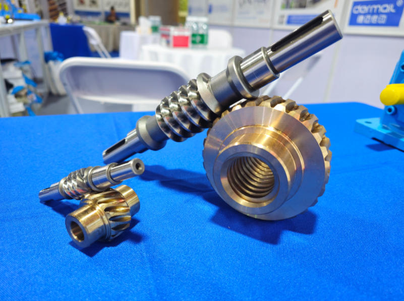
1. Importance of Proper Meshing Clearance
The meshing clearance between a worm gear and a worm is the space between the teeth of the two components when they are in contact during operation. An appropriate clearance is essential for several reasons:
- Smooth Operation: Excessive clearance can lead to noise, vibration, and erratic motion as the gears engage and disengage abruptly. On the other hand, insufficient clearance can cause binding, increased friction, and overheating, which may damage the gears over time.
- Efficiency: A well - adjusted clearance minimizes power losses due to friction, thereby improving the overall efficiency of the mechanical system.
- Longevity: Proper clearance reduces wear and tear on the gear teeth, extending the service life of both the worm gear and the worm.
2. Initial Measurement of Meshing Clearance
Before making any adjustments, it is necessary to measure the existing meshing clearance. The following are common methods for initial measurement:
2.1 Lead Wire Method
- Materials Required: Thin lead wires of known diameter, a feeler gauge, and a marking tool.
- Procedure:
- Mark several points around the circumference of the worm gear where the measurement will be taken.
- Place a lead wire between the teeth of the worm gear and the worm at each marked point.
- Rotate the worm gear slightly to ensure proper engagement of the lead wire.
- Remove the lead wire and measure its compressed thickness using a feeler gauge. The average of these measurements gives an indication of the meshing clearance at different points around the gear.
2.2 Dial Indicator Method
- Materials Required: A dial indicator with a suitable mounting bracket, a precision straight edge, and a known - thickness shim.
- Procedure:
- Mount the dial indicator on a stable part of the assembly, ensuring that its plunger is in contact with the tooth surface of the worm gear.
- Place a shim of known thickness between the worm gear and the worm at a reference point.
- Zero the dial indicator.
- Remove the shim and observe the reading on the dial indicator. This reading represents the initial meshing clearance at that point. Repeat the process at multiple points around the gear to get a comprehensive understanding of the clearance distribution.
3. Adjustment Procedures
Once the initial meshing clearance has been measured, adjustments can be made using the following methods:
3.1 Adjusting the Position of the Worm Gear
- Axial Adjustment:
- Many worm - gear assemblies are designed with provisions for axial adjustment of the worm gear. This can be achieved through the use of shims or adjusting screws.
- If the measured clearance is too large, add shims between the worm - gear housing and the bearing support to move the worm gear axially towards the worm. Conversely, if the clearance is too small, remove some shims or loosen the adjusting screws and move the worm gear away from the worm.
- After making the adjustment, re - measure the meshing clearance using the same method as before to ensure that it is within the specified range.
- Radial Adjustment:
- In some cases, radial adjustment of the worm gear may be necessary. This can be done by adjusting the position of the bearing that supports the worm - gear shaft.
- If the clearance is uneven around the circumference of the gear, it may indicate a misalignment in the radial direction. By adjusting the bearing position, the worm gear can be re - centered relative to the worm, achieving a more uniform meshing clearance.
3.2 Adjusting the Position of the Worm
- Axial Adjustment of the Worm:
- Similar to the worm gear, the worm can also be adjusted axially. This is often done by moving the worm - shaft bearing housing.
- If the clearance needs to be increased, move the worm axially away from the worm gear by adjusting the bearing housing. To decrease the clearance, move the worm towards the worm gear.
- After each adjustment, check the meshing clearance and ensure that the worm and worm gear are properly aligned.
- Angular Adjustment of the Worm:
- In some high - precision applications, angular adjustment of the worm may be required to correct for misalignment that can cause uneven meshing clearance.
- This can be achieved by using adjustable mounts or shims to change the angle of the worm - shaft relative to the worm - gear axis. However, angular adjustment is more complex and should only be attempted by experienced technicians.
4. Final Inspection and Testing
After making the necessary adjustments, a final inspection and testing should be carried out:
- Visual Inspection: Check for any signs of abnormal wear, misalignment, or damage to the gear teeth. Ensure that all components are properly secured and that there are no loose parts.
- Functional Testing: Run the worm - gear mechanism at a low speed initially and gradually increase the speed to the normal operating range. Listen for any unusual noises, such as grinding, clicking, or whining, which may indicate improper meshing. Also, check for excessive vibration or heat generation.
- Re - measurement: Re - measure the meshing clearance at multiple points around the gear to confirm that it remains within the specified tolerance after testing.
Conclusion
Adjusting the meshing clearance of worm gears and worms during assembly is a critical step in ensuring the reliable and efficient operation of mechanical systems. By using appropriate measurement methods and following systematic adjustment procedures, technicians can achieve the optimal meshing clearance, thereby enhancing the performance and longevity of screw Jack worm - gear mechanisms. Regular maintenance and periodic re - adjustment may also be necessary to account for wear and changes in operating conditions over time.


Tel:+86-317-7369999
E-mail: demai@demai.org
Mobile:+86-18653450543 (Wechat)
Address:No. 6, Haihe Road, economic development zone, Wuqiao County, Cangzhou City, Hebei Province

点击右上角
分享给朋友吧
Copyright ©2023 All Rights Reserved Hebei Demai Transmission Machinery Co.,Ltd.
Copyright ©2025 All Rights Reserved Hebei Demai Transmission Machinery Co.,Ltd.
