
Installation Guide for Dual-input Shaft Electric Linear Actuator
2026-04-26 15:27:10
Click:
“
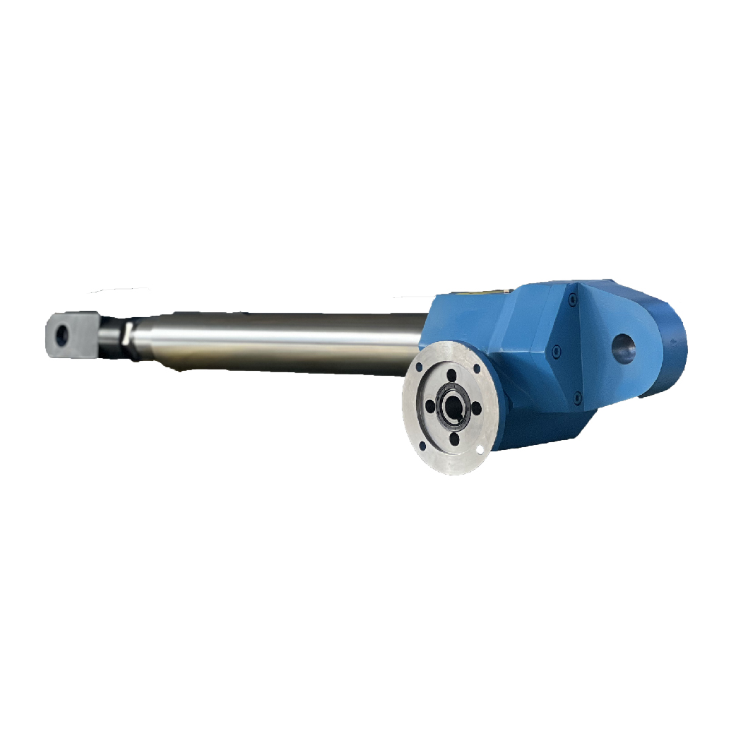
The dual-input shaft electric linear actuator is a flexible and high-precision linear motion device, featuring two independent input shafts that support electric and manual dual drive modes.
”
The dual-input shaft electric linear actuator is a flexible and high-precision linear motion device, featuring two independent input shafts that support electric and manual dual drive modes. Correct installation is critical to ensuring its stable operation, precise positioning, and long service life. This installation guide provides step-by-step instructions, technical requirements, and key precautions for the dual-input shaft electric linear actuator, applicable to all industrial and commercial installation scenarios. Following this guide strictly will help avoid installation errors, reduce equipment failure risks, and ensure the actuator performs optimally in various application environments.
1. Pre-Installation Preparation
Adequate preparation before installation lays the foundation for smooth installation and stable operation. Complete all preparation steps carefully to avoid delays or potential safety hazards during the installation process.
1.1 Inspect the Actuator and Accessories
- Unpack the dermail transmission dual-input shaft electric linear actuator and check for any damage during transportation, such as housing deformation, input shaft bending, screw scratches, motor damage, or wire breakage. If any damage is found, stop installation immediately and contact the supplier for repair or replacement.
- Verify that all accessories (mounting brackets, bolts, washers, couplings, handwheels, connecting wires, etc.) are complete and intact, and match the actuator’s specifications. Ensure the input shafts, couplings, and connecting components are free of burrs, rust, or foreign objects that may affect transmission and installation.
- Check the actuator’s lubrication status: the gearbox is pre-filled with long-acting lubricating grease at the factory. Confirm the oil level through the oil sight glass (if equipped) and ensure there is no oil leakage. If the lubrication is insufficient or contaminated, add or replace the specified lubricating grease before installation.
- Test the manual backup function (if equipped): install the handwheel on one input shaft and rotate it manually to confirm the actuator’s output end moves smoothly without jamming, ensuring the manual drive system works normally.
1.2 Prepare the Installation Site and Tools
- Select a flat, stable installation surface that can bear the actuator’s weight and the maximum load it will carry. The installation surface must be free of unevenness, cracks, or loose debris to ensure the actuator is mounted stably without vibration during operation.
- Clear the installation area of obstacles, especially around the two input shafts and the actuator’s output end, to ensure sufficient operation space for connecting motors, handwheels, or transmission components, and to facilitate later maintenance and operation.
- Prepare the required tools: torque wrench, level, measuring tape, caliper, screwdriver, wrench, wire stripper, and lifting equipment (if the actuator is heavy). Ensure all tools are calibrated and in good condition to guarantee installation accuracy and safety.
- If the actuator is installed in a wet, dusty, or corrosive environment, prepare protective accessories (such as waterproof covers, dust covers) in advance to prevent damage to internal components.
1.3 Confirm Installation Orientation and Load Direction
Determine the installation orientation (horizontal, vertical, or inverted) according to the application requirements, and confirm the load direction (push or pull) to ensure the actuator’s screw, nut, and bearing system can withstand the load correctly. Mark the installation position, the connection points of the input shafts, and the output end to avoid misalignment during installation.
2. Step-by-Step Installation Procedures
Follow the below steps in sequence to ensure correct installation of the dual-input shaft electric linear actuator. Do not skip any steps or modify the installation sequence without authorization.
2.1 Mount the Actuator to the Installation Base
- Place the actuator on the pre-marked installation position, adjust the actuator to be level using a level (horizontal and vertical deviation ≤0.5mm/m), and ensure the actuator’s housing is closely attached to the installation base without gaps.
- Align the mounting holes of the actuator’s housing with the holes on the installation base. Insert the specified mounting bolts, put on washers, and tighten the bolts evenly with a torque wrench according to the recommended torque. Do not over-tighten the bolts to avoid damaging the actuator’s housing or the installation base.
- For vertical installation, ensure the actuator’s output end is vertically downward or upward (according to load requirements) and the input shafts are horizontal, to avoid uneven stress on the internal components.
2.2 Connect the Input Shafts
The alignment of the two input shafts is critical to the transmission stability of the dual-input shaft electric linear actuator. Improper alignment will cause uneven load on the gears and bearings, leading to increased noise, wear, and even equipment failure.
- Electric Drive Connection: Align the motor output shaft with one of the actuator’s input shafts using a coupling. Ensure the coaxiality of the two shafts (coaxiality deviation ≤0.1mm) and the parallelism of the end faces (end face runout ≤0.05mm). Use a caliper or dial indicator to check the alignment, and adjust the motor position if necessary. Tighten the coupling bolts evenly to ensure a secure connection.
- Manual Drive Connection: Install the handwheel or crank on the other input shaft, ensuring the connection is tight and there is no looseness. Rotate the handwheel manually to check if the input shaft rotates smoothly without jamming or abnormal noise.
- If both input shafts are connected to motors or transmission components, ensure the two input shafts are coaxial and the transmission directions are consistent. Install a protective cover on the input shafts and couplings to prevent accidental injury during operation.
2.3 Connect the Load to the Output End
- Connect the load to the actuator’s output end using appropriate connecting components (such as flanges, brackets, or pins). Ensure the load is centered on the actuator’s axis to avoid eccentric load, which may cause bending of the screw or damage to the bearing system.
- Check the connection between the load and the output end to ensure it is tight and reliable. For heavy loads, add anti-loosening devices (such as lock nuts or split pins) to prevent the load from slipping during operation.
- Adjust the position of the actuator’s output end to the initial working position (middle of the stroke is recommended) to avoid the output end being in the extreme position during the first operation, which may cause overload.
2.4 Connect the Power Supply and Control System
- Before connecting the power supply, confirm that the power supply voltage, frequency, and phase sequence match the actuator’s specifications. Cut off the main power supply to avoid electric shock during wiring.
- Connect the motor wires of the actuator to the control system and power supply according to the wiring diagram provided by the manufacturer. Ensure the wiring is correct, tight, and insulated to avoid short circuits or poor contact.
- If the actuator is equipped with a stroke limit switch, connect the limit switch wires to the control system to ensure it can stop the actuator when the output end reaches the stroke limit, preventing over-stroke damage.
- After wiring, check the wiring again to confirm no wrong connections or loose wires. Install a protective cover on the wiring terminal to prevent dust, moisture, or accidental contact.
2.5 Install Safety and Auxiliary Components
- Install stroke limit switches (if not pre-installed) at the upper and lower limit positions of the actuator’s output end to prevent the output end from exceeding the stroke range, which may damage the actuator or the load.
- For vertical installation, install a safety nut (if equipped) on the screw to provide secondary protection against load drop in case of screw failure.
- If the installation environment is dusty, humid, or corrosive, install a protective cover or bellows on the screw and output end to prevent foreign objects from entering the gearbox or damaging the screw surface.
3. Key Installation Technical Requirements
To ensure the actuator’s performance and safety, the following technical requirements must be strictly followed during installation:
- Coaxiality Requirement: The coaxiality deviation between the input shaft and the connected motor/transmission shaft shall not exceed 0.1mm; the coaxiality deviation between the two input shafts of the actuator shall not exceed 0.08mm.
- Levelness Requirement: The horizontal and vertical levelness of the actuator during installation shall not exceed 0.5mm/m to avoid uneven load distribution and transmission interference.
- Bolt Torque Requirement: Use the specified torque to tighten the mounting bolts and connecting bolts; over-tightening or under-tightening will affect the installation stability. The recommended torque is based on the bolt size and material, which can be referred to the technical parameters.
- Eccentric Load Requirement: The load must be centered on the actuator’s axis; the eccentric load shall not exceed 10% of the rated load, otherwise, it will reduce the actuator’s service life and may cause safety hazards.
- Wiring Requirement: The power supply and control system wiring must be correct and insulated; wrong wiring will damage the motor and control system, leading to equipment failure.
- Lubrication Requirement: Ensure the gearbox is filled with the specified lubricating grease before installation; do not use incompatible lubricants, which will damage the internal gears and bearings.
4. Post-Installation Inspection and Test Run
After completing the installation, a comprehensive inspection and test run must be carried out to confirm that the actuator is installed correctly and can operate normally.
4.1 Post-Installation Inspection
- Recheck the installation position, levelness, and bolt tightness of the actuator to ensure there is no looseness or misalignment.
- Check the connection of the input shafts, couplings, load, and wiring to ensure they are tight and reliable; check the safety components (limit switches, safety nuts) to ensure they are installed correctly and can work normally.
- Inspect the gearbox for oil leakage; if there is oil leakage, check the oil seal and tighten the relevant bolts or replace the oil seal.
- Confirm that the manual drive system (handwheel) rotates smoothly and the electric drive system is correctly wired.
4.2 Test Run
- Empty Load Test: Turn on the power supply, operate the actuator in empty load mode (electric drive) to run the output end through the full stroke twice. Check if the input shafts rotate smoothly, the output end moves linearly without jamming, and there is no abnormal noise or vibration. Record the operation status.
- Manual Drive Test: Cut off the power supply, use the handwheel to rotate the input shaft, and run the output end through the full stroke twice. Check if the manual drive is smooth and the output end moves normally without jamming.
- Light Load Test: Apply 25% of the rated load to the actuator, run it through the full stroke twice, and check the transmission stability, load holding performance, and safety components. Ensure the self-locking function is reliable when the actuator stops at any position.
- Rated Load Test: Apply the rated load to the actuator, run it through the full stroke once, and check the transmission efficiency, noise, temperature rise, and load holding performance. The temperature rise of the gearbox and motor shall not exceed 40℃, and the noise shall not exceed 80dB.
- If any abnormal phenomenon (such as jamming, abnormal noise, oil leakage, or load sliding) is found during the test run, stop the operation immediately, cut off the power supply, check the cause, and rectify it before continuing the test run.
Conclusion
The installation of the dual-input shaft electric linear actuator is a systematic process that requires strict compliance with pre-installation preparation, standard installation procedures, and key technical requirements. Proper installation not only ensures the actuator’s precise positioning, stable transmission, and long service life but also minimizes safety hazards and later maintenance costs. By following the installation guide detailed in this article, installation personnel can complete the installation correctly and efficiently, enabling the dual-input shaft electric linear actuator to play its optimal performance in various industrial applications, such as multi-point synchronous motion, heavy-load positioning, and emergency backup operation.


Tel:+86-317-7369999
E-mail: demai@demai.org
Mobile:+86-18653450543 (Wechat)
Address:No. 6, Haihe Road, economic development zone, Wuqiao County, Cangzhou City, Hebei Province

点击右上角
分享给朋友吧
Copyright ©2023 All Rights Reserved Hebei Demai Transmission Machinery Co.,Ltd.
Copyright ©2025 All Rights Reserved Hebei Demai Transmission Machinery Co.,Ltd.
